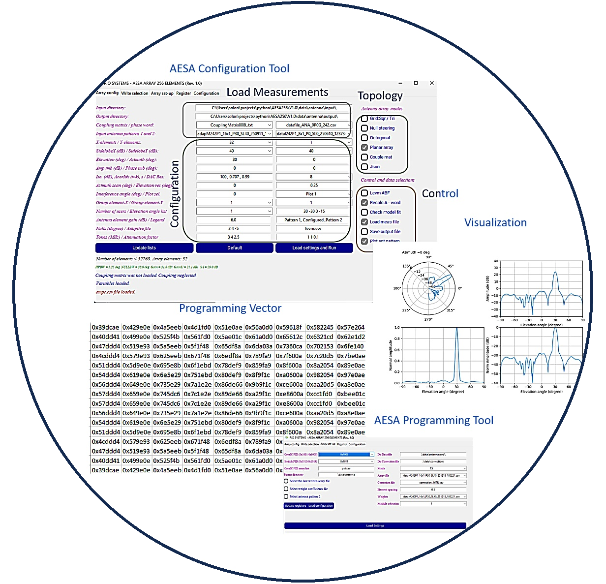
TOOLS
A wide range of Python‑based tools were developed to support the integration and testing of AESA systems, including automated measurement platforms, antenna beam‑pattern evaluation under realistic operating conditions, AESA programming environments, and hardware‑in‑the‑loop setups for subsystem assessment.
CHARACTERIZATION AND AUTOMATIZATION
Unlike standard RF devices with only a few configuration options, core IC elements provide extensive programmability that directly influences RF‑signal conditioning, overall system performance, antenna beam patterns, and side‑lobe levels. As a result, comprehensive device‑level measurements are required to characterize their behavior across a wide range of operating conditions. The volume of measurements and operating scenarios involved is far too large to be captured within a single datasheet.
defined as
NMEAS=NCH360θSTEPFNUMNASIC(1)
Where NCH is the number of channels, θSTEP is the phase step, FNUM is the number of frequencies and NASIC is the number of Core ICs. For a single ASIC with 8 channels, evaluated at a single frequency with a 1-degree phase step, the total number of measurement points is 2880. Such a large volume of data necessitates a fully automated measurement setup.
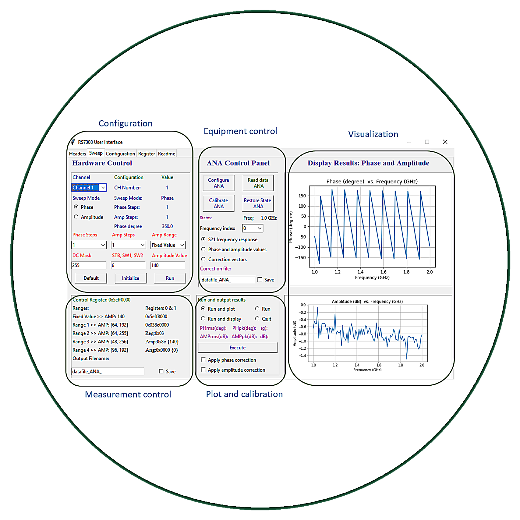
Key capabilities of the core IC characterization and automated toolset include:
- Automated core‑IC measurements adaptable to any programmed vector via SCPI commands
- Generation of programmable vectors under realistic environmental conditions
- Creation of complex error‑vector profiles
- Direct export of results in Touchstone (.S2P) format for seamless RF‑system integration
- Phase and amplitude calibration functionality
- USB‑based control and communication interface
AESA TOOLBOX
A comprehensive software toolbox for programming Active Electronically Scanned Array (AESA) systems significantly streamlines the calibration of the antenna’s beam pattern under real operational conditions. Accurate calibration is essential because even small impairments in the assignment of the complex excitation coefficients, whether due to quantization errors, thermal drift, mutual coupling, or hardware nonlinearities, can distort the intended phase and amplitude distribution across the array. These deviations manifest as beam‑squint errors, elevated sidelobe levels, reduced main‑beam gain, and, in severe cases, complete degradation of the synthesized radiation pattern.
By providing automated routines for coefficient estimation, error compensation, and adaptive correction, such a toolbox incorporates the primary array impairments directly into the design and calibration process. This integration ensures that amplitude and phase mismatches, mutual coupling effects, and hardware‑induced nonlinearities are accounted for early, allowing the synthesized excitation coefficients to remain robust against environmental variations and component imperfections. As a result, the array maintains stable beamforming performance throughout its operational envelope, ultimately enhancing system reliability and electromagnetic efficiency.
Applications in SATCOM terminals for LEO satellites, where precise beam pointing and high tracking speeds are required, demand highly accurate determination of the array’s performance. In these systems, the antenna must continuously steer and update its beam to follow rapidly
moving satellites, often with tight pointing budgets and strict sidelobe constraints to avoid interference with adjacent beams or neighboring constellations. Any mismatch in the excitation coefficients, stemming from hardware variability, thermal drift, or dynamic environmental conditions, can directly translate into pointing errors, degraded link margins, and reduced spectral efficiency. Therefore, robust calibration tools that model and compensate for array impairments are essential to ensure stable beamforming, reliable satellite acquisition, and consistent communication performance throughout the fast‑changing geometry of LEO operations.
Similar effects arise in radar systems, where errors in the estimation of the complex excitation coefficients lead to beam‑squint, elevated sidelobe levels, and overall distortion of the synthesized radiation pattern. Increased sidelobe levels further degrade system performance by allowing more energy to leak into undesired directions, making the radar more susceptible to jamming, deceptive interference, and clutter returns.